Docs
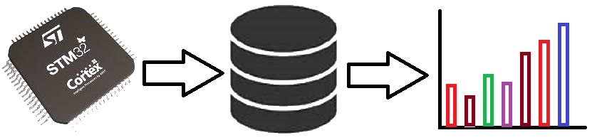
Micro-controllers, wireless transmission and database
STM32 LORA text transmission
I have used two sets of STM32 and Ebyte 915MHz UART LORA Module to transmit and receive data between long distance. This LORA module does not need library. We can simply use HAL_UART_Transmit() and HAL_UART_Receive() to transmit and receive. When receiving we need to decode the data from character to integer. Manufacturer sets Channel, Address and key to default value so no need to change these until we complete basic circuit and do a distance testing. It will work out of the box. Make sure to use both modules with same part number. E220-900T22D module is rated for 5km distance. Because I used low voltage of 3.3V VCC, I was able to get about 500m (half km) easily without line of sight using about 25mW power.
Some countries uses different frequencies and power limitation for LORA transmission. After finding out these you can get the matching module from https://www.ebyte.com. Items can be purchased from https://www.aliexpress.com/store/5489003. I bought my items from https://www.aliexpress.com/item/1005002116919184.html and the antenna from https://www.aliexpress.com/item/32737896089.html For in-house testing we do not need the antenna. If we do not use antennas, we need to switch the power off for few minutes every hour to cool the module. The reason is RF power will be returned back to module if no antenna found and it will produce heat.
Prerequisites
This project assumes you have already installed STM32CubeIDE. You need to have previously done a basic blink sketch with blue-pill using STM32CubeIDE. I have made a complete video from installing STM32CubeIDE to LED blink program. You can watch it by clicking this link. https://www.youtube.com/watch?v=kXg467nVd_A
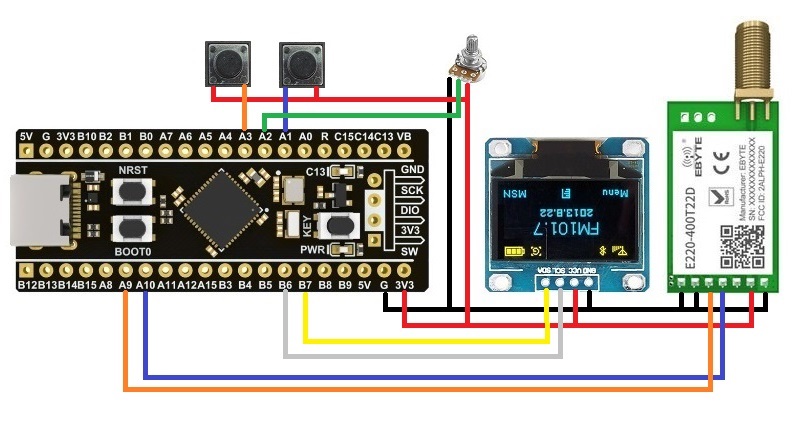
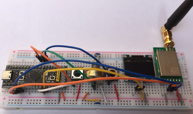
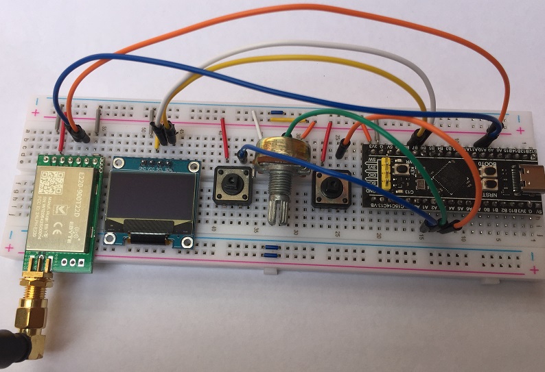
Wiring Diagram
STM32CubeIDE Settings
ADC1 - IN2 (tick)
Parameter Settings --> ADC Settings --> Continuous Conversion Mode (Enabled)
Set PA1 to GPIO_EXTI1
Set PA3 to GPIO_EXTI3
Click NVIC → EXTI line1 interrupt → Enabled (Tick)
Click NVIC → EXTI line3 interrupt → Enabled (Tick)
Click GPIO → Select PA1 → GPIO Pull-up/Pull-down → Pull-down
Click GPIO → Select PA3 → GPIO Pull-up/Pull-down → Pull-down
Enable USART1 asynchronous
Parameter Settings --> Basic Parameters --> Baud rate 9600
NVIC Settings --> USART1 global interrupt --> (Tick)
Click connectivity --> Click I2C1
For I2C select I2C
Configuration --> Parameter Settings
For I2C speed select Fast Mode
Libraries
Inside Core/Inc Folder if STM32F1xx
fonts.h ssd1306.hInside Core/Inc Folder if STM32F4xx
fonts.h ssd1306.hInside Core/Src Folder
fonts.c ssd1306.cAdditional code on top of STM32CubeIDE generated code
/* USER CODE BEGIN Includes */
#include "fonts.h"
#include "ssd1306.h"
/* USER CODE END Includes */

/* USER CODE BEGIN PV */
uint32_t previousTick = 0;
uint16_t readValue;
uint8_t charValue;
uint8_t singleChar[1] = {0};
uint8_t dataBuffer[20] = {0};
uint8_t dataIndex = 0;
uint8_t txBuffer[20] = {0};
uint8_t rxBuffer[20] = {0};
uint8_t rxIndex = 0;
uint8_t rxData;
/* USER CODE END PV */

  /* USER CODE BEGIN 2 */
  SSD1306_Init();
  HAL_UART_Receive_IT(&huart1,&rxData,1);
  /* USER CODE END 2 */

  /* Infinite loop */
  /* USER CODE BEGIN WHILE */
  while (1)
  {
    HAL_ADC_Start(&hadc1);
    HAL_ADC_PollForConversion(&hadc1,1000);
    readValue = HAL_ADC_GetValue(&hadc1);
    HAL_ADC_Stop(&hadc1);
    // Convert readValue 0-4095 to charValue 32 to 95
    charValue = readValue/65 +32;
    singleChar[0]=charValue;
    SSD1306_GotoXY (0, 0);
    SSD1306_Puts ((char *)rxBuffer, &Font_11x18, 1);
    SSD1306_GotoXY (0, 20);
    SSD1306_Puts ((char *)dataBuffer, &Font_11x18, 1);
    SSD1306_GotoXY (53,37);
    SSD1306_Puts ((char *)singleChar, &Font_16x26, 1);
    SSD1306_UpdateScreen();
    HAL_Delay(50);
    /* USER CODE END WHILE */

    /* USER CODE BEGIN 3 */
  }
  /* USER CODE END 3 */

/* USER CODE BEGIN 4 */
void HAL_GPIO_EXTI_Callback(uint16_t GPIO_Pin)
{
  if (GPIO_Pin == GPIO_PIN_3 && (HAL_GetTick() - previousTick > 600))
  {
    txBuffer[dataIndex]=charValue;
    dataBuffer[dataIndex++]=charValue;
    txBuffer[dataIndex]=13;
    HAL_UART_Transmit_IT(&huart1,(uint8_t *)txBuffer,dataIndex+1);
    previousTick = HAL_GetTick();
  }
  else if (GPIO_Pin == GPIO_PIN_1 && (HAL_GetTick() - previousTick > 600))
  {
    dataIndex--;
    dataBuffer[dataIndex]=0;
    txBuffer[dataIndex]=13;
    HAL_UART_Transmit_IT(&huart1,(uint8_t *)txBuffer,dataIndex+1);
    SSD1306_Clear();
    previousTick = HAL_GetTick();
  }
}
void HAL_UART_RxCpltCallback(UART_HandleTypeDef *huart)
{
  if(huart->Instance==USART1)
  {
    // if the character received is other than 'enter' ascii13, save the data in buffer
    if(rxData!=13)
    {
      if(rxIndex==0)
      {
        memset(rxBuffer,0,sizeof(rxBuffer));
      }
      rxBuffer[rxIndex++]=rxData;
    }
    else
    {
      SSD1306_Clear();
      rxIndex=0;
    }
    HAL_UART_Receive_IT(&huart1,&rxData,1); // Enabling interrupt receive again
  }
}
/* USER CODE END 4 */
ASCII Table
Dec  Char                           Dec  Char     Dec  Char     Dec  Char
---------                           ---------     ---------     ----------
  0  NUL (null)                      32  SPACE     64  @         96  `
  1  SOH (start of heading)          33  !         65  A         97  a
  2  STX (start of text)             34  "         66  B         98  b
  3  ETX (end of text)               35  #         67  C         99  c
  4  EOT (end of transmission)       36  $         68  D        100  d
  5  ENQ (enquiry)                   37  %         69  E        101  e
  6  ACK (acknowledge)               38  &         70  F        102  f
  7  BEL (bell)                      39  '         71  G        103  g
  8  BS  (backspace)                 40  (         72  H        104  h
  9  TAB (horizontal tab)            41  )         73  I        105  i
 10  LF  (NL line feed, new line)    42  *         74  J        106  j
 11  VT  (vertical tab)              43  +         75  K        107  k
 12  FF  (NP form feed, new page)    44  ,         76  L        108  l
 13  CR  (carriage return)           45  -         77  M        109  m
 14  SO  (shift out)                 46  .         78  N        110  n
 15  SI  (shift in)                  47  /         79  O        111  o
 16  DLE (data link escape)          48  0         80  P        112  p
 17  DC1 (device control 1)          49  1         81  Q        113  q
 18  DC2 (device control 2)          50  2         82  R        114  r
 19  DC3 (device control 3)          51  3         83  S        115  s
 20  DC4 (device control 4)          52  4         84  T        116  t
 21  NAK (negative acknowledge)      53  5         85  U        117  u
 22  SYN (synchronous idle)          54  6         86  V        118  v
 23  ETB (end of trans. block)       55  7         87  W        119  w
 24  CAN (cancel)                    56  8         88  X        120  x
 25  EM  (end of medium)             57  9         89  Y        121  y
 26  SUB (substitute)                58  :         90  Z        122  z
 27  ESC (escape)                    59  ;         91  [        123  {
 28  FS  (file separator)            60  <         92  \        124  |
 29  GS  (group separator)           61  =         93  ]        125  }
 30  RS  (record separator)          62  >         94  ^        126  ~
 31  US  (unit separator)            63  ?         95  _        127  DEL
Advanced setup (Optional)
You can download RF-Setting software and manual from https://www.ebyte.com/en/data-download.html?id=579 For this particular module Address range is 0~65535; Channel range is 0~83; Key rage is 0~65535. You can set combination of different Address and Keys to secure transmission. On top of it, you can use encrypted data and/or checksum bits as well.
I have made a seperate video about how to set frequency and keys. It is here https://youtu.be/6vIYaawRQ2g