Docs
Micro-controllers, wireless transmission and database
UART between STM32 using STM32CubeIDE
Prerequisites
This project assumes you have already installed STM32CubeIDE. You need to have previously done a basic blink sketch with blue-pill using STM32CubeIDE. I have made a complete video from installing STM32CubeIDE to LED blink program. You can watch it by clicking this link. https://www.youtube.com/watch?v=kXg467nVd_A
Wiring Diagram
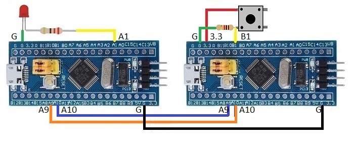
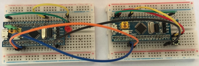
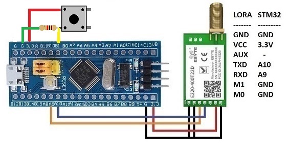
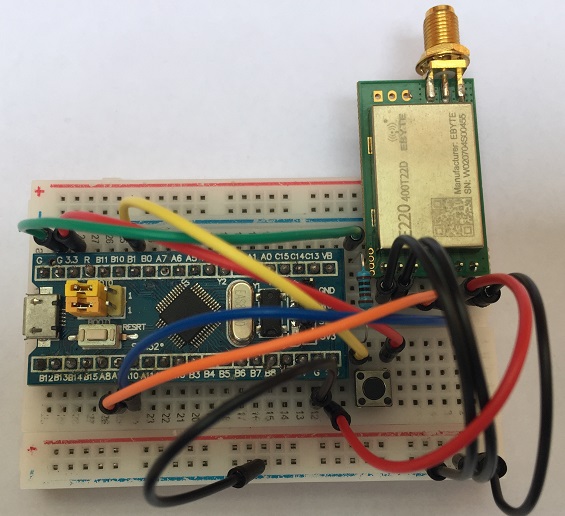
For Module with Button
STM32CubeIDE Settings
Enable USART1 asynchronous
Parameter Settings --> Basic Parameters --> Baud rate 9600
Set PB1 to GPIO_Input
Additional code on top of STM32CubeIDE generated code
/* USER CODE BEGIN 0 */
uint8_t charToTransmit[1];
/* USER CODE END 0 */

  /* USER CODE BEGIN WHILE */
  while (1)
  {
    if(HAL_GPIO_ReadPin(GPIOB, GPIO_PIN_1) == GPIO_PIN_RESET)
    {
      charToTransmit[0] = 48; // 48 is ascii character for zero
    }
    else
    {
      charToTransmit[0] = 49; // 49 is ascii character for one
    }
    HAL_UART_Transmit(&huart1, charToTransmit, 1, 100);
    HAL_Delay(200);
    /* USER CODE END WHILE */

    /* USER CODE BEGIN 3 */
  }
  /* USER CODE END 3 */
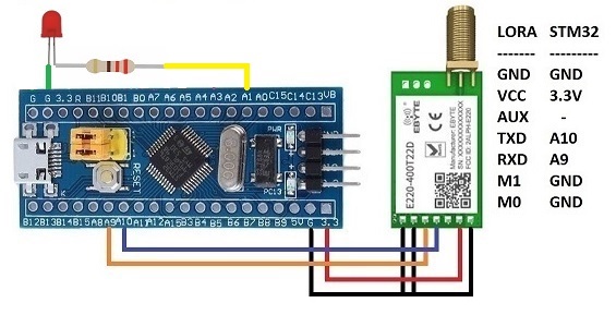
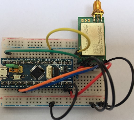
For Module with LED
STM32CubeIDE Settings
Enable USART1 asynchronous
Parameter Settings --> Basic Parameters --> Baud rate 9600
Set PA1 to GPIO_Output
Additional code on top of STM32CubeIDE generated code
/* USER CODE BEGIN 0 */
uint8_t receivedData[1];
/* USER CODE END 0 */
 while (1)
  {
    HAL_UART_Receive(&huart1, receivedData, 1, 100);
    if (receivedData[0] == '0'){
      HAL_GPIO_WritePin(GPIOA, GPIO_PIN_1, 0);
    } else if (receivedData[0] == '1'){
      HAL_GPIO_WritePin(GPIOA, GPIO_PIN_1, 1);
    }
    /* USER CODE END WHILE */

    /* USER CODE BEGIN 3 */
  }
  /* USER CODE END 3 */
For LoRa Module