Docs
Micro-controllers, wireless transmission and database

L298N Motor with Blue Pill using STM32CubeIDE
Prerequisites
This project assumes you have already installed STM32CubeIDE. You need to have previously done a basic blink sketch with blue-pill using STM32CubeIDE. I have made a complete video from installing STM32CubeIDE to LED blink program. You can watch it by clicking this link. https://www.youtube.com/watch?v=kXg467nVd_A
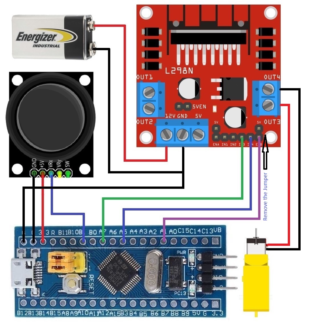
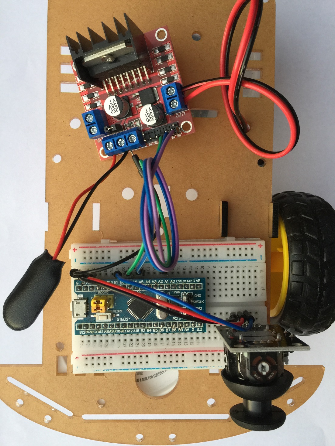
Wiring Diagram
STM32CubeIDE Settings
Click Timer → Click TIM2 →
Clock Source set to Internal Clock
Channel2 set to PWM Generation CH2
Configuration → Parameter Settings →
Prescaler set to 127
Counter Period 625
ADC1 - IN9 (tick)
Parameter Settings --> ADC Settings --> Continuous Conversion Mode (Enabled)
Set PA5 and PA7 to GPIO_Output
Additional code on top of STM32CubeIDE generated code
  /* USER CODE BEGIN 2 */
  HAL_ADC_Start(&hadc1);  //PB1
  HAL_TIM_PWM_Start(&htim2, TIM_CHANNEL_2); //PA1 TIM2 CH2
  uint16_t readValue;
  int speed;
  HAL_GPIO_WritePin(GPIOA, GPIO_PIN_7, 0);
  HAL_GPIO_WritePin(GPIOA, GPIO_PIN_5, 0);
  /* USER CODE END 2 */

  /* Infinite loop */
  /* USER CODE BEGIN WHILE */
  while (1)
  {
    HAL_ADC_PollForConversion(&hadc1,1000);
    readValue = HAL_ADC_GetValue(&hadc1);
    if (readValue < 1790) {
      HAL_GPIO_WritePin(GPIOA, GPIO_PIN_7, 0);
      HAL_GPIO_WritePin(GPIOA, GPIO_PIN_5, 1);
      speed = (readValue - 1790) * (-1) / 3;
    } else if (readValue > 2220) {
      HAL_GPIO_WritePin(GPIOA, GPIO_PIN_5, 0);
      HAL_GPIO_WritePin(GPIOA, GPIO_PIN_7, 1);
      speed = (readValue - 2220) / 3;
    } else {
      speed = 0;
    }
    __HAL_TIM_SET_COMPARE(&htim2,TIM_CHANNEL_2, speed);
    HAL_Delay(50);
    /* USER CODE END WHILE */

    /* USER CODE BEGIN 3 */