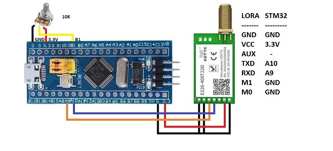
I have used two sets of STM32 and Ebyte 433MHz UART LORA Module to transmit and receive data between long distance. This LORA module does not need library. We can simply use HAL_UART_Transmit() and HAL_UART_Receive() to transmit and receive. When receiving we need to decode the data from character to integer. Manufacturer sets Channel, Address and key to default value so no need to change these until we complete basic circuit and do a distance testing. It will work out of the box. Make sure to use both modules with same part number. E220-400T22D module is rated for 5km distance. Because I used low voltage of 3.3V VCC, I was able to get about 500m (half km) easily without line of sight using about 25mW power.
Some countries uses different frequencies and power limitation for LORA transmission. After finding out these you can get the matching module from https://www.ebyte.com. Inexpensive items can be purchased from https://www.aliexpress.com/store/5489003. I bought my items from https://www.aliexpress.com/item/1005002091320352.html and the antenna from https://www.aliexpress.com/item/1005001530239330.html. For in-house testing we do not need the antenna. If we do not use antennas, we need to switch the power off for few minutes every hour to cool the module. The reason is RF power will be returned back to module if no antenna found and it will produce heat.
Even though these modules can be used for transmit and receive simultaneously, I used one of them for transmission and the other one for receiving only for simplicity. You can do a modification for feedback transmission for acknowledgement. I used a potentiometer for data source. You can use any sensors or any data for transmission. You can use the received data to save in a database or control something using MOSFET or relay.
This project assumes you have already installed STM32CubeIDE and OpenOCD. You need to have previously done a basic blink sketch with blue-pill using STM32CubeIDE. I have made a complete video from installing STM32CubeIDE to LED blink program. You can watch it by clicking this link. https://www.youtube.com/watch?v=kXg467nVd_A
Enable USART1 asynchronous
Parameter Settings --> Basic Parameters --> Baud rate 9600
ADC1 - IN9 (tick)
Parameter Settings --> ADC Settings --> Continuous Conversion Mode (Enabled)
// Additional transmitter code on top of STM32CubeIDE generated code

/* USER CODE BEGIN 0 */
uint16_t readValue;
uint8_t charToTransmit[1];
/* USER CODE END 0 */

  /* USER CODE BEGIN 2 */
  HAL_ADC_Start(&hadc1);
  /* USER CODE END 2 */

 /* USER CODE BEGIN WHILE */
  while (1)
  {
	  HAL_ADC_PollForConversion(&hadc1,1000);
	  readValue = HAL_ADC_GetValue(&hadc1);
          // divide by 800 to convert 0~4095 to 0~5
          // Add 48 to convert number 0~5 to character '0' ~ '5'
	  charToTransmit[0] = readValue / 800 + 48;
	  HAL_UART_Transmit(&huart1, charToTransmit, 1, 100);
	  HAL_Delay(500);
    /* USER CODE END WHILE */

    /* USER CODE BEGIN 3 */
  }
  /* USER CODE END 3 */
Enable USART1 asynchronous
Parameter Settings --> Basic Parameters --> Baud rate 9600
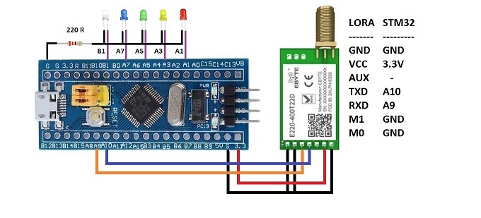
Set PA1, PA3, PA5, PA7 and PB1 to GPIO_Output
// Additional Receiver code on top of STM32CubeIDE generated code

/* USER CODE BEGIN 0 */
uint8_t receivedData[1];
/* USER CODE END 0 */

  /* USER CODE BEGIN WHILE */
  while (1)
  {
	  HAL_UART_Receive(&huart1, receivedData, 1, 100);
	  if (receivedData[0] == '0'){
		  HAL_GPIO_WritePin(GPIOB, GPIO_PIN_1, 0);
		  HAL_GPIO_WritePin(GPIOA, GPIO_PIN_7, 0);
		  HAL_GPIO_WritePin(GPIOA, GPIO_PIN_5, 0);
		  HAL_GPIO_WritePin(GPIOA, GPIO_PIN_3, 0);
		  HAL_GPIO_WritePin(GPIOA, GPIO_PIN_1, 0);
	  }
	  else if (receivedData[0] == '1'){
		  HAL_GPIO_WritePin(GPIOB, GPIO_PIN_1, 1);
		  HAL_GPIO_WritePin(GPIOA, GPIO_PIN_7, 0);
		  HAL_GPIO_WritePin(GPIOA, GPIO_PIN_5, 0);
		  HAL_GPIO_WritePin(GPIOA, GPIO_PIN_3, 0);
		  HAL_GPIO_WritePin(GPIOA, GPIO_PIN_1, 0);
	  }
	  else if (receivedData[0] == '2'){
		  HAL_GPIO_WritePin(GPIOB, GPIO_PIN_1, 0);
		  HAL_GPIO_WritePin(GPIOA, GPIO_PIN_7, 1);
		  HAL_GPIO_WritePin(GPIOA, GPIO_PIN_5, 0);
		  HAL_GPIO_WritePin(GPIOA, GPIO_PIN_3, 0);
		  HAL_GPIO_WritePin(GPIOA, GPIO_PIN_1, 0);
	  }
	  else if (receivedData[0] == '3'){
		  HAL_GPIO_WritePin(GPIOB, GPIO_PIN_1, 0);
		  HAL_GPIO_WritePin(GPIOA, GPIO_PIN_7, 0);
		  HAL_GPIO_WritePin(GPIOA, GPIO_PIN_5, 1);
		  HAL_GPIO_WritePin(GPIOA, GPIO_PIN_3, 0);
		  HAL_GPIO_WritePin(GPIOA, GPIO_PIN_1, 0);
	  }
	  else if (receivedData[0] == '4'){
		  HAL_GPIO_WritePin(GPIOB, GPIO_PIN_1, 0);
		  HAL_GPIO_WritePin(GPIOA, GPIO_PIN_7, 0);
		  HAL_GPIO_WritePin(GPIOA, GPIO_PIN_5, 0);
		  HAL_GPIO_WritePin(GPIOA, GPIO_PIN_3, 1);
		  HAL_GPIO_WritePin(GPIOA, GPIO_PIN_1, 0);
	  }
	  else if (receivedData[0] == '5'){
		  HAL_GPIO_WritePin(GPIOB, GPIO_PIN_1, 0);
		  HAL_GPIO_WritePin(GPIOA, GPIO_PIN_7, 0);
		  HAL_GPIO_WritePin(GPIOA, GPIO_PIN_5, 0);
		  HAL_GPIO_WritePin(GPIOA, GPIO_PIN_3, 0);
		  HAL_GPIO_WritePin(GPIOA, GPIO_PIN_1, 1);
	  }
	  HAL_Delay(100);
    /* USER CODE END WHILE */

    /* USER CODE BEGIN 3 */
  }
  /* USER CODE END 3 */
You can download RF-Setting software and manual from https://www.ebyte.com/en/data-download.html?id=579&pid=211#load. For this particular module Address range is 0~65535; Channel range is 0~83; Key rage is 0~65535. You can set combination of different Address and Keys to secure transmission. On top of it, you can use encrypted data and/or checksum bits as well.