I have used two sets of ESP32 and Ebyte 433MHz UART LORA Module to transmit and receive data between long distance. This LORA module does not need library. We can simply use Serial.print() and Serial.read() to transmit and receive. When receiving we need to decode the data from character to integer. I used HardwareSerial Two instead of Serial. Manufacturer sets Channel, Address and key to default value so no need to change these until we complete basic circuit and do a distance testing. It will work out of the box. Make sure to use both modules with same part number. E220-400T22D module is rated for 5km distance. Because I used low voltage of 3.3V VCC, I was able to get about 500m (half km) easily without line of sight using about 25mW power.
Some countries uses different frequencies and power limitation for LORA transmission. After finding out these you can get the matching module from https://www.ebyte.com. Inexpensive items can be purchased from https://www.aliexpress.com/store/5489003. I bought my items from https://www.aliexpress.com/item/1005002091320352.html and the antenna from https://www.aliexpress.com/item/1005001530239330.html. For in-house testing we do not need the antenna. If we do not use antennas, we need to switch the power off for few minutes every hour to cool the module. The reason is RF power will be returned back to module if no antenna found and it will produce heat.
Even though these modules can be used for transmit and receive simultaneously, I used one of them for transmission and the other one for receiving only for simplicity. You can do a modification for feedback transmission for acknowledgement. I used a potentiometer for data source. You can use any sensors or any data for transmission. You can use the received data to save in a database or control something using MOSFET or relay.
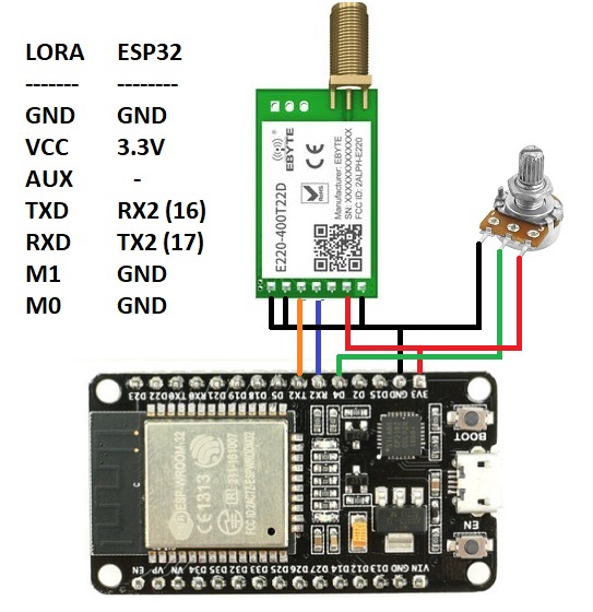
// Transmitter code
HardwareSerial SerialAT(1);
#define KNOB 4
int readVal;

void setup() {
  SerialAT.begin(9600,SERIAL_8N1,16,17);
}

void loop() {
  readVal = analogRead(KNOB);
  SerialAT.println(readVal);
  delay(500);
}
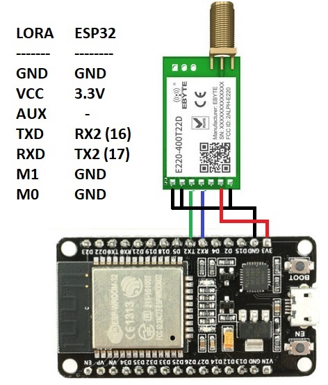
// Receiver code
HardwareSerial SerialAT(1);

void setup() {
  Serial.begin(9600);
  SerialAT.begin(9600,SERIAL_8N1,16,17);
}

void loop() {
  if (SerialAT.available()) {
    Serial.write(SerialAT.read());
  }
}
File → Preferences → Type https://dl.espressif.com/dl/package_esp32_index.json in Additional Boards Manager URLs
Tools → Board → Boards Manager → Type esp32 and click install button next to esp32 by Espressif Systems
Tools → Board → ESP32 Arduino → ESP32 Wrover Module
Tools → Port (Select the correct port)
While receiving in UART, the data comes in single character at a time. For example the integer number 3256 comes as char “3” then char “2” then char “5” and then char “6” finally a new line char “\r”. To convert these into the number again we need to decode this. I have shown a simple decoder below. Just replace
if (SerialAT.available()) {
  Serial.write(SerialAT.read());
}
with the following codes
if (SerialAT.available()) {
  static char input[8];
  static uint8_t i;
  char c = SerialAT.read ();
  if ( c != '\r' && i < 7 ) // assuming "Carriage Return" is chosen as the line ending character
    input[i++] = c;
  else
  {
    input[i] = '\0';
    i = 0;
    int receivedNumber = atoi( input ); // Now the receivedNumber is an integer we can store or
                                        // use this value to control devices
  }
}
You can download RF-Setting software and manual from https://www.ebyte.com/en/data-download.html?id=579&pid=211#load. For this particular module Address range is 0~65535; Channel range is 0~83; Key rage is 0~65535. You can set combination of different Address and Keys to secure transmission. On top of it, you can use encrypted data and/or checksum bits as well.